


MSI-H Series Linear Position Sensor with Profibus Output
The MSI-H series is a rod-type, high-precision, absolute, non-contact magnetostrictive linear position sensor with a measuring range from 25 to 3800 mm.
Position measurement is performed using ring-type position magnets that move along the waveguide without physical contact. The sensor flange is made of high-quality stainless steel and designed for long-term operation in demanding industrial environments.
Price on request
Design features
- Adjustable node address and zero position
- Modular design allows fast replacement without depressurizing the hydraulic circuit
- Compatible with all Temposonics position magnets and selected BALLUFF magnets
- Zero position offset of 50 mm, 30 mm, or customer-specific value
- Absolute linear measurement (output signals proportional to magnet displacement)
- LED status indicator for diagnostics
- High accuracy: resolution up to 5 µm
- Measuring length from 25 to 3800 mm (1 mm increments)
- Linearity < 0.01 %
- Repeatability < 0.001 %
- Operating temperature up to +85 °C
- Optional operating pressure up to 800 bar
- Protection class IP67
- The sensor supports the use of water-resistant and Teflon cables.
Measurement start point from the sensor housing by default
Configurator

MSI-H
.
_
.
_
.
_
.
_
.
P
_
_
_
MSI-H Series Linear Position Sensor with Profibus Output, order code:
Scope of delivery
THE SCOPE OF SUPPLY INCLUDES: | |
Linear position sensor | |
Certificate of Conformity | |
Manual | |
Warranty card | |
Mating connectors and magnets for the sensor must be ordered separately! | |
Product ordering code
TECHNICAL REQUIREMENTS FOR ORDER PLACEMENT | ||||||||||||||||||||
1 | 2 | 3 | 4 | 5 | 6 | 7 | 8* | 8* | ||||||||||||
MSI-H | . | S | . | 0 | 5 | 0 | 0 | . | T | . | D60 | . | P | 1 | 0 | 1 | ||||
1 | Series: MSI-H - Rod-type | |||||||||||||||||||
2 | Flange type: M – M18 × 1.5, rod Ø10 mm S – 3/4”-16 UNF, rod Ø10 mm R – M18 × 1.5 with M4 thread on rod end, Ø10 mm Z – 3/4”-16 UNF with M4 thread on rod end, Ø10 mm T – 3/4”-16 UNF with raised face, Ø10 mm V – M18 × 1.5 with FKM seal, Ø10 mm U – 3/4”-16 UNF with raised face, FKM seal, Ø10 mm H – 3/4”-16 UNF, FKM seal, Ø10 mm L – 3/4”-16 UNF, rod Ø7 mm K – M18 × 1.5, rod Ø7 mm | |||||||||||||||||||
3 | Measuring range: 0025...3800 mm, 5 mm step Other lengths available on request | |||||||||||||||||||
4 | Zero point: T - 50 mm B - 30 mm | |||||||||||||||||||
5 | Connection: D53 – Interface: 5-pin male and female connector, M12-B Power supply: 4-pin male connector, M8 D63 – 6-pin male and female connector, M16 S103 – Interface: 5-pin male and female connector, M12-B Power supply: 3-pin male connector, M8 D73 – Cover with 3 cable glands | |||||||||||||||||||
6 | Output signal: P - Profibus-DP | |||||||||||||||||||
7 | Position measurement mode: 101 - multi-position measurement (2–3 positions) 102 - single-position measurement (standard) | |||||||||||||||||||
8* | Node address | |||||||||||||||||||
9* | Number of positions: Z02 - 2 positions Z03 - 3 positions *Only for P101 | |||||||||||||||||||
By default, the sensor node address is 125.
This address can be changed at any time using the USB-Profibus programmer, item no. MSI-280 640.
If the required address information is provided at the time of order, the sensor will be configured during production.
Technical specifications
OUTPUT PARAMETERS | ||||
Measured value | Position | |||
Operating range, L | 25 — 3800 mm, 1 mm step | |||
Displacement speed | Any | |||
Update rate | 0.5 ms up to 1200 mm; 1.0 ms up to 2400 mm; 2.0 ms up to 3800 mm; | |||
Status diagnostics | LEDs next to the connector | |||
INTERFACE | ||||
Digital interface | Profibus-DP bus according to ISO 74498 | |||
Data transfer protocol | Profibus-DP (EN-50170) | |||
Number of magnets | 1-3 | |||
Max cable length | Cable length, m: Baud rate, Mbit/s: | <100 | <200 | <400 |
For stable operation, it is recommended to use a cable no longer than 20 meters | ||||
POSITION MEASUREMENT ACCURACY | ||||
Linearity | < ± 0.01 % F.S. (minimum ± 40 µm) | |||
Repeatability | < ± 0.001 % F.S. (minimum ± 2.5 µm) | |||
OPERATING CONDITIONS | ||||
Operating temperature | -40 °C…+85 °C | |||
Rated pressure | 350 bar, 600 bar peak (optional 800 bar) | |||
Humidity | 90 % rel. humidity, no condensation | |||
Ingress protection | IP65, IP67 at cable outlet | |||
MATERIALS | ||||
Sensor electronics housing | Aluminum, plastic | |||
Sensor rod | Stainless steel ASTM A269-13 / TP304l (10x1.5) | |||
Flange | Stainless steel 08Х18Н10 / AISI 304 | |||
MOUNTING | ||||
Mounting position | Any orientation. For horizontal installation of sensors with an operating range exceeding 1000 mm, the rod must be supported or fixed at the end | |||
Flange parameters | Flange thread M18х1.5 or 3/4" - 16 UNF | |||
Position magnet mounting | Mounting hardware and screws made of non-magnetic material | |||
ELECTRICAL CONNECTION | ||||
Operating voltage | 24 (- 15 / +20 %) V DC | |||
Reverse polarity protection | up to –30 V DC | |||
Overvoltage protection | up to 36 V DC | |||
Current consumption | 50…140 mA (depending on sensor length) | |||
Insulation resistance | 500 V DC (between sensor housing and 0 V DC) | |||
STANDARDS, EMC TESTS | ||||
Shock test | 100 g, single shock according to IEC 60068-2-7 | |||
Vibration test | 15 g / 10–2000 Hz according to IEC 60068-2-6 | |||
EMC tests | GOST R IEC 61326-1-2014 | |||
Connection: D53 connector
PIN ASSIGNMENT | PIN | FUNCTION |
 M12-B female connector (view from sensor side) | 1 | VP+5 (bus terminator) |
2 | RxD/TxD-N (bus) | |
3 | DGnd (bus terminator) | |
4 | RxD/TxD-P (bus) | |
5 | Shielded cable braid | |
 M12-B male connector (view from sensor side) | 1 | Not applicable |
2 | RxD/TxD-N (bus) | |
3 | Not applicable | |
4 | RxD/TxD-P (bus) | |
5 | Shielded cable braid | |
 M8 male connector (view from sensor side) | 1 | +24 VDC (-15% / +20%) |
2 | Not applicable | |
3 | 0 VDC (power supply) | |
4 | Not applicable |
Connection: D63 connector
PIN ASSIGNMENT | PIN | FUNCTION |
 M16 female connector (view from sensor side) | 1 | RxD/TxD-N (bus) |
2 | RxD/TxD-P (bus) | |
3 | DGnd (bus terminator) | |
4 | VP+5 (bus terminator) | |
5 | +24 VDC (-15% / +20%) | |
6 | 0 VDC (power supply) | |
 M16 male connector (view from sensor side) | 1 | RxD/TxD-N (bus) |
2 | RxD/TxD-P (bus) | |
3 | Not applicable | |
4 | Not applicable | |
5 | +24 VDC (-15% / +20%) | |
6 | 0 VDC (power supply) |
Connection: S103 connector
PIN ASSIGNMENT | PIN | FUNCTION |
M12-B female connector (view from sensor side) | 1 | VP+5 (bus terminator) |
2 | RxD/TxD-N (bus) | |
3 | DGnd (bus terminator) | |
4 | RxD/TxD-P (bus) | |
5 | Shielded cable braid | |
M12-B male connector (view from sensor side) | 1 | Not applicable |
2 | RxD/TxD-N (bus) | |
3 | Not applicable | |
4 | RxD/TxD-P (bus) | |
5 | Shielded cable braid | |
 M8 male connector (view from sensor side) | 1 | +24 VDC (-15% / +20%) |
3 | 0 VDC (power supply) | |
4 | Shielded cable braid |
Connection: D73 connector
CONNECTION DIAGRAM | PIN ASSIGNMENT | PIN | FUNCTION |
 | Х1 | 1 | RxD/TxD-P (bus) |
2 | RxD/TxD-N (bus) | ||
Х2 | 1 | RxD/TxD-N (bus) | |
2 | RxD/TxD-P (bus) | ||
Х3 | 1 | Preset | |
2 | - | ||
Х4 | 1 | +24 VDC (-15% / +20%) | |
2 | 0 VDC (power supply) | ||
Х5 | 1 | 0 VDC (power supply) | |
2 | +24 VDC (-15% / +20%) |
Preset Input:
• Logic level “1” > +8 V
• Logic level “0” < +2 V
• Permissible input range: up to ±35 V
• Input resistance: 5 kΩ
Using BCD address switches S1 (101) and S2 (100), the node address of the PROFIBUS sensor can be set from 3 to 99.
If the PROFIBUS sensor is the last node on the PROFIBUS line, the DIP switches T1 and T2 for the integrated PROFIBUS terminator must be switched ON.
Interface
The sensor complies with all PROFIBUS-DP requirements (EN 50170).
All measurements performed by the sensor are absolute and transmitted via RS485 at a maximum speed of 12 Mbit/s.
The PROFIBUS-DP bus allows connection of up to 32 devices on a single segment. In addition to transmitting the main measured parameter (position), PROFIBUS-DP provides advanced functions for diagnostics and configuration. These parameters are loaded onto the bus via a GSD file (device-specific technical specifications).
Key characteristics of the PROFIBUS-DP sensor:
Data transmitted by the sensor:
-
Absolute position measurement
-
Sensor status
-
Error information (magnet status)
Configurable parameters:
-
Measurement direction: forward/backward
-
Resolution: 5, 50, 100, 200, 500, 1000 µm
-
Data transmission mode: synchronous, asynchronous
-
Various data formats
Multi-position measurement
OPERATING MODES |
Data Exchange When measuring with multiple magnets, 1 byte of status data and 3 bytes of position data are transmitted per cycle. The status data byte contains: an error bit and the number of positions in the current measurement. |
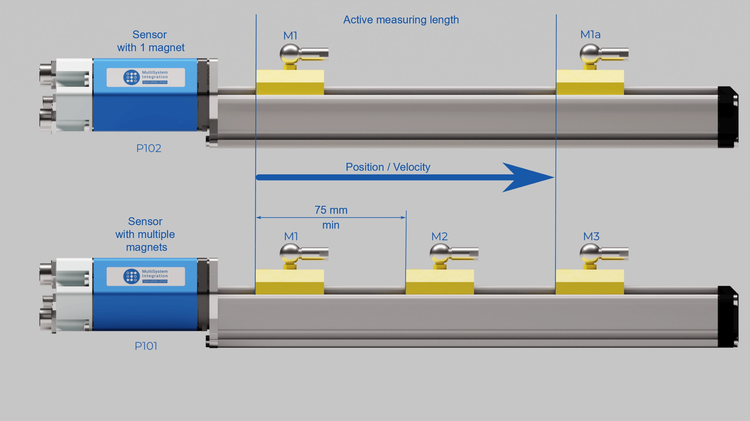 P102 Measurements with one magnet (standard) P101 Measurements with multiple magnets, 1–3 pcs Simultaneous measurements with up to 3 magnets, minimum distance between magnets 76 mm. |
Connection example
DIGITAL INTERFACE PROFIBUS D53 |
 |
DIGITAL INTERFACE PROFIBUS D53 WITH BUS CONNECTOR |
 |
Setting
Status diagnostics
LED DIAGNOSTICS | GREEN | RED | STATUS |
 | Off | Off | No power supply or sensor fault |
On | Off | Normal operation | |
On | On | No position magnet or incorrect number of magnets |
Interchangeability
| MSI | Balluff | Temposonics |
|---|---|---|
| MSI-H EtherCAT | BTL7 -Y/Z- Series – EtherCAT | R-Series V RH5 EtherCAT |
| MSI-H Profinet | BTL7 -Y/Z- Series - Profinet | R-Series V RH5 Profinet |
| MSI-H Analog | BTL7 -Y/Z- Series - Analog voltage | R-Series V RH5 Analog |
| MSI-H SSI | BTL7 -Y/Z- Series – SSI | R-Series V RH5 SSI |
| MSI-H Analog | BTL7 -Y/Z- Series - Analog current | R-Series V RH5 Analog |
| MSI-H SSI | BTL7 -A/B- Series – SSI | R-Series V RH5 SSI |
| MSI-H EtherCAT | BTL7 -A/B- Series – EtherCAT | R-Series V RH5 EtherCAT |
| MSI-H Profinet | BTL7 -A/B- Series – Profinet | R-Series V RH5 Profinet |
| MSI-H Analog | BTL7 -A/B- Series - Analog voltage | R-Series V RH5 Analog |
| MSI-H Analog | BTL7 -A/B- Series - Analog current | R-Series V RH5 Analog |
| MSI-H CANopen | BTL5 -Y/Z- Series – CANopen | R-Series RH CANopen |
| MSI-H Profinet | BTL5 -Y/Z- Series – Profibus | R-Series V RH5 Profinet |
| MSI-H CANopen | BTL5 -A/B- Series - CANopen | R-Series RH CANopen |
| MSI-H Profibus | BTL5 -A/B- Series - Profibus | R-Series RH Profibus |
| MSI-H Start/Stop | BTL7 -BE/BF- Serie - Digital | E-Series EH Start/Stop |
| MSI-H SSI | BTL7 -BE/BF- Serie – SSI | R-Series V RH5 SSI |
| MSI-H Start/Stop | BTL7 -ZE/ZF- Serie – Digital | E-Series EH Start/Stop |
| MSI-H SSI | BTL7 -ZE/ZF- Serie – SSI | R-Series V RH5 SSI |
| MSI-H Start/Stop | BTL7 -CE- Serie – Digital | E-Series EH Start/Stop |
| MSI-H SSI | BTL7 -CE- Serie – SSI | R-Series V RH5 SSI |
| MSI-H Start/Stop | BTL7 -CD- Series – Digital | E-Series EH Start/Stop |
| MSI-H Analog | BTL7 -CD- Series - Analog voltage | R-Series V RH5 Analog |
| MSI-H SSI | BTL7 -CD- Series – SSI | R-Series V RH5 SSI |
| MSI-H Analog | BTL7 -CD- Series - Analog current | R-Series V RH5 Analog |
| MSI-H CANopen | BTL5 -W- Series – CANopen | R-Series RH CANopen |
| MSI-H CANopen | BTL5 -WB- Series - CANopen | R-Series RH CANopen |
| MSI-H Start/Stop | BTL5 -WB- Series – Digital | E-Series EH Start/Stop |
| MSI-H Start/Stop | BTL5 -W- Series – Digital | E-Series EH Start/Stop |
| MSI-H CANopen | BTL5 -HB- Series – CANopen | R-Series RH CANopen |
| MSI-H Start/Stop | BTL5 -HB- Series – Digital | E-Series EH Start/Stop |
| MSI-H CANopen | BTL5 -K- Series – CANopen | R-Series RH CANopen |
| MSI-H Start/Stop | BTL5 -K- Series – Digital | E-Series EH Start/Stop |
| MSI-H DeviceNet | R-Series RH DeviceNet | |
| MSI-H DeviceNet | R-Series RP DeviceNet |


Downloads
Technical Documentation


Technical drawing
Certificates
Software
Inquiry Form
Contact a specialist


 Configurator
 Navigation
 Rod-Type
