


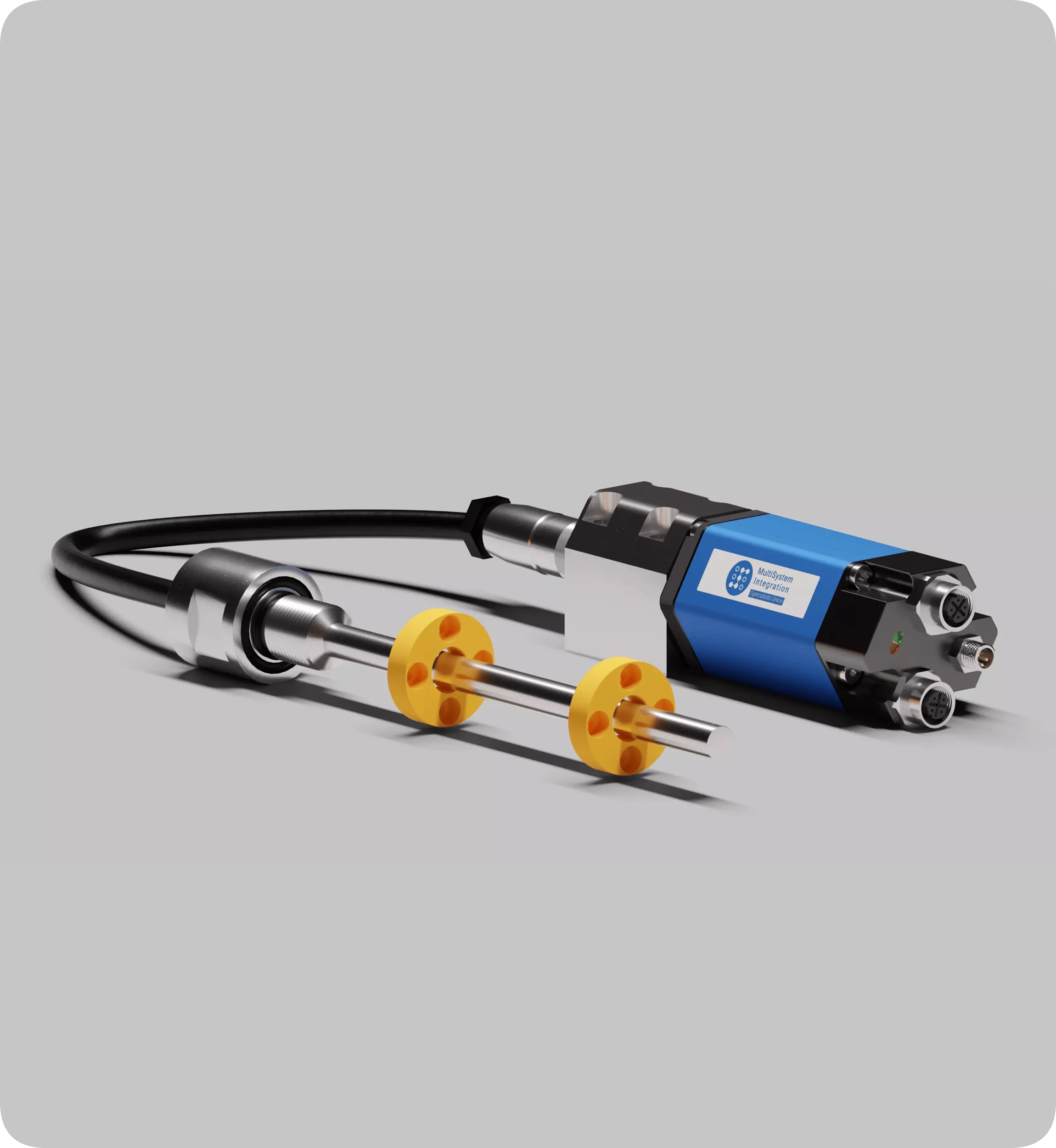
MSI-D Series Linear Position Sensor with Profinet Output
Rod-style, high-precision, absolute, non-contact magnetostrictive position sensor with remote electronics, featuring a measuring range from 25 to 3800 mm. Position measurement is performed using ring-type position magnets that move along the waveguide without physical contact. The sensor flange is made of high-quality stainless steel and is designed for long-term industrial operation.
Price on request
Design features
- The modular sensor design provides advantages for installation in confined spaces and simplifies service and maintenance of the MSI-D series sensors.
- The sensor consists of two separate parts: the electronics and the waveguide are spaced by up to 350 mm with bottom connection and up to 600 mm with side connection.
- Compatible with all Temposonics position magnets and selected BALLUFF magnets
- Zero position offset of 50 mm, 30 mm, or customer-specific value
- Absolute linear measurement (output signals proportional to magnet displacement)
- LED status indicator for diagnostics
- High accuracy: resolution up to 1 µm
- Measuring length from 25 to 3800 mm (1 mm increments)
- Linearity < 0.01 %
- Repeatability < 0.001 %
- Operating temperature up to +85 °C
- Optional operating pressure up to 800 bar
- Protection class IP67
Configurator
MSI-D
.
_
_
.
_
.
_
.
_
.
U
_
_
_
MSI-D Series Linear Position Sensor with Profinet Output, order code:
Scope of delivery
THE SCOPE OF SUPPLY INCLUDES: | |
Linear position sensor | |
Certificate of Conformity | |
Manual | |
Warranty card | |
Mating connectors and magnets for the sensor must be ordered separately! | |
Product ordering code
TECHNICAL REQUIREMENTS FOR ORDER PLACEMENT | |||||||||||||||||||||||
1 | 2 | 3 | 4 | 5 | 6 | 7 | 8 | 9* | 10* | ||||||||||||||
MSI-D | . | 1 | D | 3 | S | . | 0 | 5 | 0 | 0 | . | T | . | D56 | . | U | 4 | 0 | 1 | ||||
1 | Series: MSI-D - Rod-style with detached electronics | ||||||||||||||||||||||
2 | Flange type: 1 - Embeddable flange Ø 34,5 mm 2 - M18x1.5 flange (standard) 3 - Embeddable flange Ø 26,92 mm | ||||||||||||||||||||||
3 | Connection type: D1S - Side connection. Polyurethane cable, 250 mm long D2S - Side connection. Polyurethane cable, 400 mm long D3S - Side connection. Polyurethane cable, 600 mm long R4B - Bottom connection. Single wires with a flat connector, length 170 mm R5B - Bottom connection. Single wires with a flat connector, length 230 mm R6B - Bottom connection. Single wires with a flat connector, length 350 mm | ||||||||||||||||||||||
4 | Measuring range: 0025...3800 mm, 1 mm step Other lengths available on request | ||||||||||||||||||||||
5 | Zero point: T - 50 mm B - 30 mm | ||||||||||||||||||||||
6 | Connection: D56 - Interface: 2 × 5-pin female connector, M12-D; Power: 4-pin male connector, M8 D58 - Interface: 2 × 5-pin female connector, M12-D; Power: 4-pin male connector, M12-A | ||||||||||||||||||||||
7 | Output signal: U - Profinet RT&IRT | ||||||||||||||||||||||
8 | Position measurement mode: 402 - multi-position measurement (2–8 positions) 401 - single-position measurement (standard) | ||||||||||||||||||||||
9* | Node address: 1...125 (factory setting 125) | ||||||||||||||||||||||
10* | Number of positions: Z02 - 2 positions ... Z08 - 8 positions *Only for U402 | ||||||||||||||||||||||
Technical specifications
OUTPUT PARAMETERS | ||||
Measured value | Position | |||
Operating range, L | 25 — 3800 mm, 1 mm step | |||
Displacement speed | Any | |||
Update rate | 0.5 ms up to 1200 mm; 1.0 ms up to 2400 mm; 2.0 ms up to 3800 mm | |||
Status diagnostics | LEDs next to the connector | |||
INTERFACE | ||||
Digital interface | Bus Profinet RT / IRT version 2.3 | |||
Data protocol | Encoder Profile 4.1 | |||
Number of magnets | 1-8 | |||
Max cable length | Сable length, m <100 Transmission speed, Mbit/s 100 | |||
For stable operation, it is recommended to use a cable no longer than 20 meters | ||||
POSITION MEASUREMENT ACCURACY | ||||
Linearity | < ± 0.01 % F.S. (minimum ± 40 µm) | |||
Repeatability | < ± 0.001 % F.S. (minimum ± 2.5 µm) | |||
OPERATING CONDITIONS | ||||
Operating temperature | -40 °C…+85 °C | |||
Rated pressure | 350 bar, 600 bar peak (optional 800 bar) | |||
Humidity | 90 % rel. humidity, no condensation | |||
Ingress protection | IP65, IP67 at cable outlet | |||
MATERIALS | ||||
Sensor electronics housing | Aluminum, plastic | |||
Sensor rod | Stainless steel ASTM A269-13 / TP304l (10x1.5) | |||
Flange | Stainless steel 08Х18Н10 / AISI 304 | |||
MOUNTING | ||||
Mounting position | Any orientation. For horizontal installation of sensors with an operating range exceeding 1000 mm, the rod must be supported or fixed at the end | |||
Flange parameters | Flange thread M18х1.5 or 3/4" - 16 UNF | |||
Position magnet mounting | Mounting hardware and screws made of non-magnetic material | |||
ELECTRICAL CONNECTION | ||||
Operating voltage | 24 V DC (–15 % / +20 %) | |||
Reverse polarity protection | up to –30 V DC | |||
Overvoltage protection | up to 36 V DC | |||
Current consumption | 50…140 mA (depending on sensor length) | |||
Insulation resistance | 500 V DC (between sensor housing and 0 V DC) | |||
STANDARDS, EMC TESTS | ||||
Shock test | 100 g, single shock according to IEC 60068-2-7 | |||
Vibration test | 15 g / 10–2000 Hz according to IEC 60068-2-6 | |||
EMC tests | GOST R IEC 61326-1-2014 | |||
Connection: D56 connector
BUS INPUT PORT №1 | PIN | FUNCTION |
 M12 female connector, D-coded (view from sensor side) | 1 | Tx (+) (bus) |
2 | Rx (+) (bus) | |
3 | Tx (-) (bus) | |
4 | Rx (-) (bus) | |
BUS OUTPUT PORT №2 | PIN | FUNCTION |
M12 female connector, D-coded (view from sensor side) | 1 | Tx (+) (bus) |
2 | Rx (+) (bus) | |
3 | Tx (-) (bus) | |
4 | Rx (-) (bus) | |
SENSOR POWER SUPPLY | PIN | FUNCTION |
 M8 male connector (view from sensor side) | 1 | +24 VDC (-15% / +20%) |
2 | Not applicable | |
3 | 0 VDC (power supply) | |
4 | Not applicable |
Connection: D58 connector
BUS INPUT PORT №1 | PIN | FUNCTION |
M12 female connector, D-coded (view from sensor side) | 1 | Tx (+) (bus) |
2 | Rx (+) (bus) | |
3 | Tx (-) (bus) | |
4 | Rx (-) (bus) | |
BUS OUTPUT PORT №2 | PIN | FUNCTION |
M12 female connector, D-coded (view from sensor side) | 1 | Tx (+) (bus) |
2 | Rx (+) (bus) | |
3 | Tx (-) (bus) | |
4 | Rx (-) (bus) | |
SENSOR POWER SUPPLY | PIN | FUNCTION |
 M12 male connector, A-coded (view from sensor side) | 1 | +24 VDC (-15% / +20%) |
2 | Not applicable | |
3 | 0 VDC (power supply) | |
4 | Not applicable |
Installation recommendations
ELECTRONICS CONNECTION OPTIONS | |
BOTTOM CONNECTION | SIDE CONNECTION |
 |  |
CONNECTION TYPE No. 1 | |
Embeddable flange Ø 34,5 mm, side connection:  | |
Embeddable flange Ø 34,5 mm, bottom connection:  | |
Installation recommendations:  | |
CONNECTION TYPE No. 2 | |
M18x1.5 flange (standard) for bottom electronics connection  | |
M18x1.5 flange (standard) for side electronics connection  | |
Installation recommendations:  | |
CONNECTION TYPE No.3 | |
Embeddable flange Ø26.92 mm for bottom electronics connection  | |
Embeddable flange Ø26.92 mm for side electronics connection  | |
Installation recommendations:  | |
EXAMPLE OF SENSOR INSTALLATION IN A HYDRAULIC CYLINDER | |
Embeddable Ø29,92 mm with bottom connection  | |
M18x1.5 flange (standard) for bottom electronics connection  | |
* The zero position is specified when ordering the sensor and can be set at a distance of 30 mm or 50 mm * Non-magnetic spacer No. 1 is required only when the zero position is set at 30 mm from the linear position sensor flange and the sensor sleeve is made of magnetic material. | |
Interface
The sensor complies with all requirements of the ProfiNET standard (IEC 61158), providing high-speed data transmission over an industrial Ethernet network. All measurements performed by the sensor are absolute and are transmitted at speeds of up to 100 Mbit/s.
The ProfiNET bus allows up to 256 devices to be connected within a single network, ensuring system flexibility and scalability. Various network topologies are supported, including star, ring, and line. Sensor parameters are loaded into the system using a GSDML file.
Sensor operating modes:
Real-Time (RT) mode:
- Provides data transmission with minimal latency.
- Suitable for applications that do not require strict synchronization.
Isochronous Real-Time (IRT) mode:
- Provides precise synchronization of devices within the network.
- Used in applications with high requirements for timing performance.
Multi-position measurement
OPERATING MODES |
Data Exchange When measuring with multiple magnets, 1 byte of status data and 3 bytes of position data are transmitted per cycle. The status data byte contains: an error bit and the number of positions in the current measurement. |
 P102 Measurements with one magnet (standard) P101 Measurements with multiple magnets, 1–3 pcs Simultaneous measurements with up to 3 magnets, minimum distance between magnets 76 mm. |
Connection example
CONNECTION EXAMPLE |
 |
Status diagnostics
LED DIAGNOSTICS | GREEN | RED | STATUS |
 | Off | Off | No power supply or sensor fault |
On | Off | Normal operation | |
On | On | No position magnet or incorrect number of magnets |
Interchangeability
| MSI | Balluff | Temposonics |
|---|---|---|
| MSI-H EtherCAT | BTL7 -Y/Z- Series – EtherCAT | R-Series V RH5 EtherCAT |
| MSI-H Profinet | BTL7 -Y/Z- Series - Profinet | R-Series V RH5 Profinet |
| MSI-H Analog | BTL7 -Y/Z- Series - Analog voltage | R-Series V RH5 Analog |
| MSI-H SSI | BTL7 -Y/Z- Series – SSI | R-Series V RH5 SSI |
| MSI-H Analog | BTL7 -Y/Z- Series - Analog current | R-Series V RH5 Analog |
| MSI-H SSI | BTL7 -A/B- Series – SSI | R-Series V RH5 SSI |
| MSI-H EtherCAT | BTL7 -A/B- Series – EtherCAT | R-Series V RH5 EtherCAT |
| MSI-H Profinet | BTL7 -A/B- Series – Profinet | R-Series V RH5 Profinet |
| MSI-H Analog | BTL7 -A/B- Series - Analog voltage | R-Series V RH5 Analog |
| MSI-H Analog | BTL7 -A/B- Series - Analog current | R-Series V RH5 Analog |
| MSI-H CANopen | BTL5 -Y/Z- Series – CANopen | R-Series RH CANopen |
| MSI-H Profinet | BTL5 -Y/Z- Series – Profibus | R-Series V RH5 Profinet |
| MSI-H CANopen | BTL5 -A/B- Series - CANopen | R-Series RH CANopen |
| MSI-H Profibus | BTL5 -A/B- Series - Profibus | R-Series RH Profibus |
| MSI-P analog или MSI-PB analog | BTL B1 - Profile PA – Analog | R-Series V RP5 analog |
| MSI-PB analog | BTL C1 - Profile PF – Analog | R-Series V RP5 analog |
| MSI-P analog или MSI-PB analog | BTL C1 - Profile PA – Analog | R-Series V RP5 analog |
| MSI-P analog или MSI-PB analog | BTL B1 - Profile PA – Analog | R-Series V RP5 analog |
| MSI-P SSI | BTL7 -P- Series – Digital | R-Series V RP5 SSI |
| MSI-PB analog | BTL7 -P- Series - Analog voltage | R-Series V RP5 analog |
| MSI-P SSI | BTL7 -P- Series – SSI | R-Series V RP5 SSI |
| MSI-PB analog | BTL7 -P- Series - Analog current | R-Series V RP5 analog |
| MSI-P EtherCAT | BTL7 -P- Series – EtherCAT | R-Series V RP5 EtherCAT |
| MSI-P Profinet | BTL7 -P- Series – Profinet | R-Series V RP5 Profinet |
| MSI-P analog или MSI-PB analog | BTL6 -PF- Series - Analog voltage | R-Series V RP5 analog |
| MSI-P analog или MSI-PB analog | BTL6 -PF- Series - Analog current | R-Series V RP5 analog |
| MSI-P или MSI-PB Start/Stop | BTL6 -A1- Series – Digital | E-Series EP2 Start/Stop |
| MSI-P EtherCAT | BTL6 -A1- Series – EtherCAT | R-Series V RP5 EtherCAT |
| MSI-P analog или MSI-PB analog | BTL6 -A1- Series - Analog voltage | R-Series V RP5 analog |
| MSI-P CANopen | BTL5 -P- Series – CANopen | E-Series RP CANopen |
| MSI-P Profibus | BTL5 -P- Series – Profibus | E-Series RP Profibus |
| MSI-P или MSI-PB Start/Stop | BTL7 -BE/BF- Serie - Digital | E-Series EP2 Start/Stop |
| MSI-P SSI | BTL7 -BE/BF- Serie – SSI | R-Series V RP5 SSI |
| MSI-P или MSI-PB Start/Stop | BTL7 -ZE/ZF- Serie – Digital | E-Series EP2 Start/Stop |
| MSI-P Profibus | BTL5 -P- Series – Profibus | E-Series RP Profibus |
| MSI-H Start/Stop | BTL7 -BE/BF- Serie - Digital | E-Series EH Start/Stop |
| MSI-H SSI | BTL7 -BE/BF- Serie – SSI | R-Series V RH5 SSI |
| MSI-H Start/Stop | BTL7 -ZE/ZF- Serie – Digital | E-Series EH Start/Stop |
| MSI-H SSI | BTL7 -ZE/ZF- Serie – SSI | R-Series V RH5 SSI |
| MSI-H Start/Stop | BTL7 -CE- Serie – Digital | E-Series EH Start/Stop |
| MSI-H SSI | BTL7 -CE- Serie – SSI | R-Series V RH5 SSI |
| MSI-H Start/Stop | BTL7 -CD- Series – Digital | E-Series EH Start/Stop |
| MSI-H Analog | BTL7 -CD- Series - Analog voltage | R-Series V RH5 Analog |
| MSI-H SSI | BTL7 -CD- Series – SSI | R-Series V RH5 SSI |
| MSI-H Analog | BTL7 -CD- Series - Analog current | R-Series V RH5 Analog |
| MSI-B Analog | BTL7 -K- Series - Analog voltage | |
| MSI-B Analog | BTL7 -K- Series - Analog current | |
| MSI-H CANopen | BTL5 -W- Series – CANopen | R-Series RH CANopen |
| MSI-H CANopen | BTL5 -WB- Series - CANopen | R-Series RH CANopen |
| MSI-H Start/Stop | BTL5 -WB- Series – Digital | E-Series EH Start/Stop |
| MSI-H Start/Stop | BTL5 -W- Series – Digital | E-Series EH Start/Stop |
| MSI-H CANopen | BTL5 -HB- Series – CANopen | R-Series RH CANopen |
| MSI-H Start/Stop | BTL5 -HB- Series – Digital | E-Series EH Start/Stop |
| MSI-H CANopen | BTL5 -K- Series – CANopen | R-Series RH CANopen |
| MSI-H Start/Stop | BTL5 -K- Series – Digital | E-Series EH Start/Stop |
| MSI-B SSI | BTL5 -K- Series – SSI | |
| MSI-F | R-Series V RF5 R-Series V RFV | |
| MSI-D | R-Series V RDV | |
| MSI-H DeviceNet | R-Series RH DeviceNet | |
| MSI-H DeviceNet | R-Series RP DeviceNet | |
| MSI-P DeviceNet | E-Series RP DeviceNet |
Downloads
Technical Documentation


Technical drawing
Certificates
Software
Inquiry Form
Contact a specialist


 Configurator
 Navigation
 Rod-Type
